Digital interface module for modular E-713 Motion Controller, 12 inputs and 12 outputs with TTL level (5 V)
E-713.IxxD0 • IxxI0 Digital Interfaces for E-713 Motion Controller
For Digital Input and Output Signals
- For modular E-713 Motion Controllers
- Maximum flexibility for high-precision motions
- 24 V nominal voltage for industrial automation
- Programmable by command
Integration of digital signals
Interface modules each with 12 digital inputs and outputs for a nominal level of 5 V or 24 V. With diagnostic option for the outputs.
Suitable for industrial use and interference-proof
The galvanic isolation and a sophisticated grounding concept provide for the highest signal integrity through protection from interference. The model with 24 V nominal level facilitates simple integration of the E-713 Motion Controller into the automation technology.
Trigger function or motor stop
The user can use commands to configure each of the digital inputs and outputs for various applications. This makes it possible to use the inputs to initiate the recording or wave generator output in the E-713 Motion Controller. Furthermore, a digital input can be used to automatically switch off the servo mode and thus trigger a motor stop in the event of a fault. The outputs can be used to output trigger signals, e.g., synchronously to the axis motion and to the wave generator output.
Modular design
The digital interface modules are intended for use in the modular E-713 Motion Controller. The modular concept makes it possible to assemble E-713 Motion Controllers exactly according to customer requirements. An E-713 Motion Controller controls in a coordinated manner up to 16 axes with various drive types. This involves the use of state-of-the-art control and linearization algorithms. Optional interface modules support motion automation.
Specifications
Specifications
Basics | E-713.ICCD0 | E-713.ICCI0 | |
---|---|---|---|
Housing type | Module without housing, 4 HP | Module without housing, 8 HP | |
Interfaces and Operation | E-713.ICCD0 | E-713.ICCI0 | |
Digital inputs | 12 | 12 | |
Digital input signal | TTL (5 V), galvanically isolated, input voltage for logic 0 is 0 V to 0.8 V, input voltage for logic 1 is 2.0 V to 5 V | 24 V nominal level, galvanically isolated, voltages > 11.2 V are detected as high level, voltages < 8.5 V are detected as low level | |
Digital outputs | 12 | 12 | |
Digital output signal | TTL (5 V), galvanically isolated, maximum output voltage for logic 0 is 0.1 V at 100 μA output current and 0.8 V at 4 mA output current, minimum output voltage for logic 1 is 4.9 V at 100 μA output current and 2.0 V at 24 mA output current | 24 V nominal level, galvanically isolated, high-side switching | |
Duration of the transition from low level to high level at the output | 0.016 µs | 5 µs | |
Electrical Properties | E-713.ICCD0 | E-713.ICCI0 | |
Current limitation per channel | — | 700 mA | |
Short-circuit proof | Yes | Yes | |
Average output current per channel | 50 mA | 500 mA | |
Current limitation across all channels, supplied internally | — | 1000 mA | |
Current limitation across all channels, supplied externally | — | 3500 mA | |
Average output current across all channels, supplied internally | 600 mA | 1000 mA | |
Average output current across all channels, supplied externally | — | 3000 mA | |
Miscellaneous | E-713.ICCD0 | E-713.ICCI0 | |
Connector digital input | HD D-sub 44 (f) | HD D-sub 44 (f) | |
Connector digital output | HD D-sub 44 (f) | HD D-sub 44 (f) | |
Operating voltage | 5 V, generated internally | 24 V, internally generated or provided externally | |
Operating temperature range | 5 to 40 °C | 5 to 40 °C | |
Overall mass | 180 g | 180 g |
Interface module with 5 V nominal level:
If nothing is connected to a digital input, the state of the digital input line is pulled to high level by an internal pull-up resistor of 10 kΩ.
The inputs and outputs are internally supplied and, when switched off, are protected against overvoltage up to 5.5 V. The inputs are protected against polarity reversal.
Interface module with 24 V nominal level:
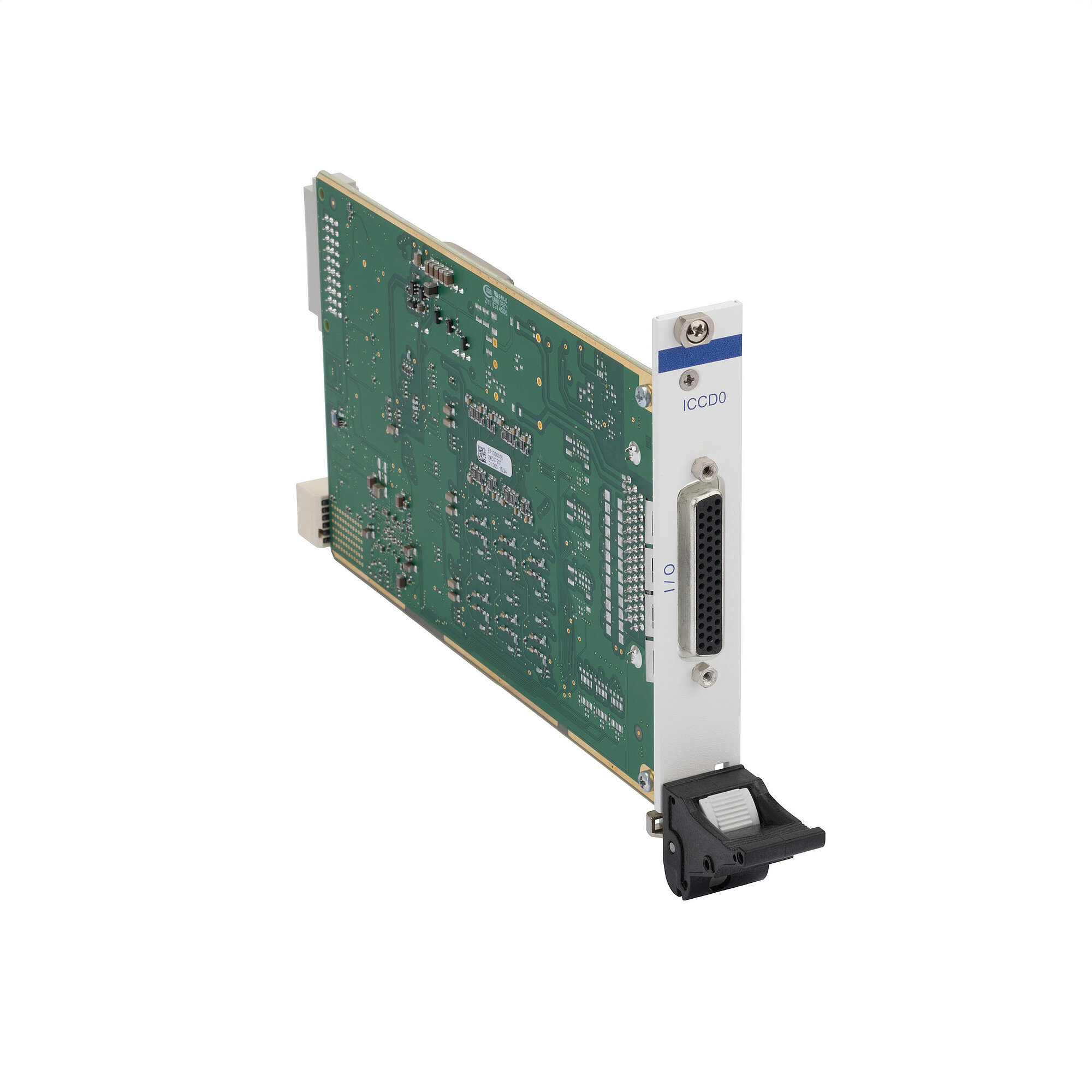
An internally generated 24-V voltage can be used to supply the outputs if a total current of 1 A is sufficient. As an alternative, an external supply with a nominal voltage of 24 V and a maximum current of 3 A can be used. The external wiring at the HD D-sub 44 (f) connector determines whether the internally generated voltage or a voltage provided externally is used.
The outputs can be operated using operating voltages of between 13 V and 30 V.
The switch-off times (high -> low) of the outputs depend on the connected load, whereas the switch-on times (low -> high) are load-independent. There may be a significant difference between the switch-on times and switch-off times of the outputs.
As of an input voltage of approx. 5 V, there is a constant current of approx. 2.26 mA at the inputs.
Ask for a free quote on quantities required, prices, and lead times or describe your desired modification.
Digital interface module for modular E-713 Motion Controller, 12 inputs and 12 outputs with 24 V nominal level