|
Housing type
|
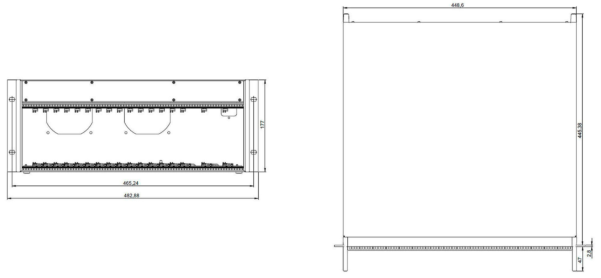
Rack insert 19" 4U
|
Rack insert 19" 4U
|
Rack insert 19" 4U
|
Rack insert 19" 4U
|
|
|
Drive type
|
PICMA®
|
PICMA®
|
PICMA®
|
PICMA®
|
|
|
Axes
|
3
|
3
|
6
|
6
|
|
|
Output channels
|
4
|
4
|
8
|
8
|
|
|
Input channels
|
3
|
3
|
6
|
6
|
|
|
Processor
|
PC-based
|
PC-based
|
PC-based
|
PC-based
|
|
|
Application-related functions
|
Makro ǀ Startup macro ǀ Data recorder
|
Makro ǀ Startup macro ǀ Data recorder ǀ Fast Alignment
|
Makro ǀ Startup macro ǀ Data recorder
|
Makro ǀ Startup macro ǀ Data recorder ǀ Fast Alignment
|
|
|
Drive functions
|
AutoZero
|
AutoZero
|
AutoZero
|
AutoZero
|
|
|
Protective functions
|
Deactivation of the voltage output in case of internal overheating ǀ Switch-off of the servo mode in case of an error ǀ Automatic motor stop
|
Deactivation of the voltage output in case of internal overheating ǀ Switch-off of the servo mode in case of an error ǀ Automatic motor stop
|
Deactivation of the voltage output in case of internal overheating ǀ Switch-off of the servo mode in case of an error ǀ Automatic motor stop
|
Deactivation of the voltage output in case of internal overheating ǀ Switch-off of the servo mode in case of an error ǀ Automatic motor stop
|
|
|
Configuration management
|
Import of parameter files ǀ Reading the ID chip ǀ Manual parameter input
|
Import of parameter files ǀ Reading the ID chip ǀ Manual parameter input
|
Import of parameter files ǀ Reading the ID chip ǀ Manual parameter input
|
Import of parameter files ǀ Reading the ID chip ǀ Manual parameter input
|
|
|
Supported ID chip
|
ID chip 2.0
|
ID chip 2.0
|
ID chip 2.0
|
ID chip 2.0
|
|
|
Motion and control
|
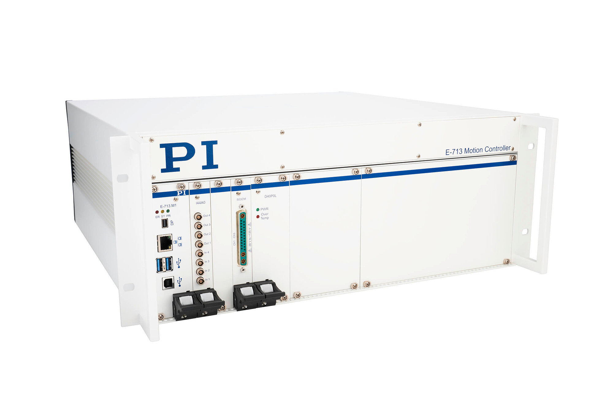
E-713 PICMA® Controller, 3 axes
|
E-713 PICMA® Controller, 3 axes, analog I/O
|
E-713 PICMA® Controller, 6 axes
|
E-713 PICMA® Controller, 6 axes, analog I/O
|
|
|
Supported sensor signal
|
analog (cap.)
|
analog (cap.)
|
analog (cap.)
|
analog (cap.)
|
|
|
Control variables
|
Position
|
Position
|
Position
|
Position
|
|
|
Maximum control frequency (servo cycle)
|
50000 Hz
|
50000 Hz
|
20000 Hz
|
20000 Hz
|
|
|
Motion types
|
Point-to-point motion ǀ Point-to-point motion with profile generator ǀ Wave generator
|
Point-to-point motion ǀ Point-to-point motion with profile generator ǀ Area scan routines ǀ Gradient search routines ǀ Wave generator
|
Point-to-point motion ǀ Point-to-point motion with profile generator ǀ Wave generator
|
Point-to-point motion ǀ Point-to-point motion with profile generator ǀ Area scan routines ǀ Gradient search routines ǀ Wave generator
|
|
|
Motion coordination
|
Coordinated multi-axis motion
|
Coordinated multi-axis motion
|
Coordinated multi-axis motion
|
Coordinated multi-axis motion
|
|
|
Interfaces and operation
|
E-713 PICMA® Controller, 3 axes
|
E-713 PICMA® Controller, 3 axes, analog I/O
|
E-713 PICMA® Controller, 6 axes
|
E-713 PICMA® Controller, 6 axes, analog I/O
|
|
|
Communication interfaces
|
TCP/IP ǀ USB
|
TCP/IP ǀ USB
|
TCP/IP ǀ USB
|
TCP/IP ǀ USB
|
|
|
On/off switch
|
Hardware switch on/off
|
Hardware switch on/off
|
Hardware switch on/off
|
Hardware switch on/off
|
|
|
Display and indicators
|
Error LED ǀ Power LED ǀ On Target LED ǀ Overtemp LED
|
Error LED ǀ Power LED ǀ On Target LED ǀ Overtemp LED
|
Error LED ǀ Power LED ǀ On Target LED ǀ Overtemp LED
|
Error LED ǀ Power LED ǀ On Target LED ǀ Overtemp LED
|
|
|
Command set
|
GCS 2.0
|
GCS 2.0
|
GCS 2.0
|
GCS 2.0
|
|
|
User software
|
PIMikroMove
|
PIMikroMove
|
PIMikroMove
|
PIMikroMove
|
|
|
Application programming interfaces
|
C, C++, C# ǀ MATLAB ǀ NI LabView ǀ Python
|
C, C++, C# ǀ MATLAB ǀ NI LabView ǀ Python
|
C, C++, C# ǀ MATLAB ǀ NI LabView ǀ Python
|
C, C++, C# ǀ MATLAB ǀ NI LabView ǀ Python
|
|
|
Linearization
|
DDL option (Dynamic Digital Linearization) ǀ 4th order polynomials
|
DDL option (Dynamic Digital Linearization) ǀ 4th order polynomials
|
DDL option (Dynamic Digital Linearization) ǀ 4th order polynomials
|
DDL option (Dynamic Digital Linearization) ǀ 4th order polynomials
|
|
|
Analog inputs
|
—
|
4
|
—
|
4
|
|
|
Analog input signal
|
—
|
±10.675 V differential, input impedance 150 kΩ, bandwidth maximum 25 kHz
|
—
|
±10.675 V differential, input impedance 150 kΩ, bandwidth maximum 25 kHz
|
|
|
Digital resolution of the analog input
|
—
|
18 bit
|
—
|
18 bit
|
|
|
Analog outputs
|
—
|
4
|
—
|
4
|
|
|
Analog output signal
|
—
|
±12.775 V, output current maximum 60 mA per output, bandwidth maximum 12 kHz
|
—
|
±12.775 V, output current maximum 60 mA per output, bandwidth maximum 12 kHz
|
|
|
Digital resolution of the analog output
|
—
|
16 bit
|
—
|
16 bit
|
|
|
Amplifier
|
E-713 PICMA® Controller, 3 axes
|
E-713 PICMA® Controller, 3 axes, analog I/O
|
E-713 PICMA® Controller, 6 axes
|
E-713 PICMA® Controller, 6 axes, analog I/O
|
|
|
Resolution DAC/voltage resolution
|
20 bit
|
20 bit
|
20 bit
|
20 bit
|
|
|
Sensor
|
E-713 PICMA® Controller, 3 axes
|
E-713 PICMA® Controller, 3 axes, analog I/O
|
E-713 PICMA® Controller, 6 axes
|
E-713 PICMA® Controller, 6 axes, analog I/O
|
|
|
Digital resolution for the sensor input
|
18 bit
|
18 bit
|
18 bit
|
18 bit
|
|
|
Sensor bandwidth
|
10 kHz
|
10 kHz
|
10 kHz
|
10 kHz
|
|
|
Electrical properties
|
E-713 PICMA® Controller, 3 axes
|
E-713 PICMA® Controller, 3 axes, analog I/O
|
E-713 PICMA® Controller, 6 axes
|
E-713 PICMA® Controller, 6 axes, analog I/O
|
|
|
Output voltage
|
-30 to +135 V
|
-30 to +135 V
|
-30 to +135 V
|
-30 to +135 V
|
|
|
Short-circuit proof
|
Yes
|
Yes
|
Yes
|
Yes
|
|
|
Average output power per channel
|
8 W
|
8 W
|
8 W
|
8 W
|
|
|
Peak output power per channel
|
25 W
|
25 W
|
25 W
|
25 W
|
|
|
Peak output power per channel, time limit
|
5 ms
|
5 ms
|
5 ms
|
5 ms
|
|
|
Average output current per channel
|
150 mA
|
150 mA
|
150 mA
|
150 mA
|
|
|
Peak output current per channel
|
250 mA
|
250 mA
|
250 mA
|
250 mA
|
|
|
Peak output current per channel, time limit
|
5 ms
|
5 ms
|
5 ms
|
5 ms
|
|
|
Miscellaneous
|
E-713 PICMA® Controller, 3 axes
|
E-713 PICMA® Controller, 3 axes, analog I/O
|
E-713 PICMA® Controller, 6 axes
|
E-713 PICMA® Controller, 6 axes, analog I/O
|
|
|
Motor/actuator connector
|
D-sub 25W3
|
D-sub 25W3
|
D-sub 25W3
|
D-sub 25W3
|
|
|
Sensor connector
|
D-sub 25W3
|
D-sub 25W3
|
D-sub 25W3
|
D-sub 25W3
|
|
|
Connector analog input
|
—
|
LEMO EPG.00.302.NLN
|
—
|
LEMO EPG.00.302.NLN
|
|
|
Connector analog output
|
—
|
LEMO EPG.00.302.NLN
|
—
|
LEMO EPG.00.302.NLN
|
|
|
Connector TCP/IP
|
RJ45 socket, 8P8C
|
RJ45 socket, 8P8C
|
RJ45 socket, 8P8C
|
RJ45 socket, 8P8C
|
|
|
Connector USB
|
USB socket type B
|
USB socket type B
|
USB socket type B
|
USB socket type B
|
|
|
Connector for supply voltage
|
IEC 60320 type C14
|
IEC 60320 type C14
|
IEC 60320 type C14
|
IEC 60320 type C14
|
|
|
Power connection
|
100 to 240 V AC ǀ 50 to 60 Hz
|
100 to 240 V AC ǀ 50 to 60 Hz
|
100 to 240 V AC ǀ 50 to 60 Hz
|
100 to 240 V AC ǀ 50 to 60 Hz
|
|
|
Power entry fuse
|
1 x T6.3AH, 250 V
|
1 x T6.3AH, 250 V
|
1 x T6.3AH, 250 V
|
1 x T6.3AH, 250 V
|
|
|
Maximum power consumption
|
330 W
|
330 W
|
330 W
|
330 W
|
|
|
Operating temperature range
|
5 to 40 °C
|
5 to 40 °C
|
5 to 40 °C
|
5 to 40 °C
|
|
|
Overall mass
|
7892 g
|
8054 g
|
8584 g
|
8746 g
|
|