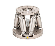
H-811.F2
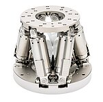
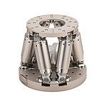
光学アライメント用の小型ヘキサポッド、取り外し可能な磁気プレート、ブラシレスDCモーター搭載、耐荷重:5 kg、速度:20 mm/s、ケーブル長:0.5 m。 接続ケーブルは同梱されていませんので、別途ご注文ください。
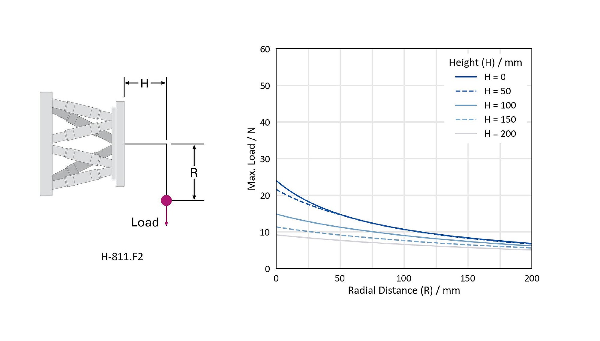
H-811.F2を水平に取り付けた場合の最大荷重
H-811.F2を垂直に取り付けた場合の最大荷重
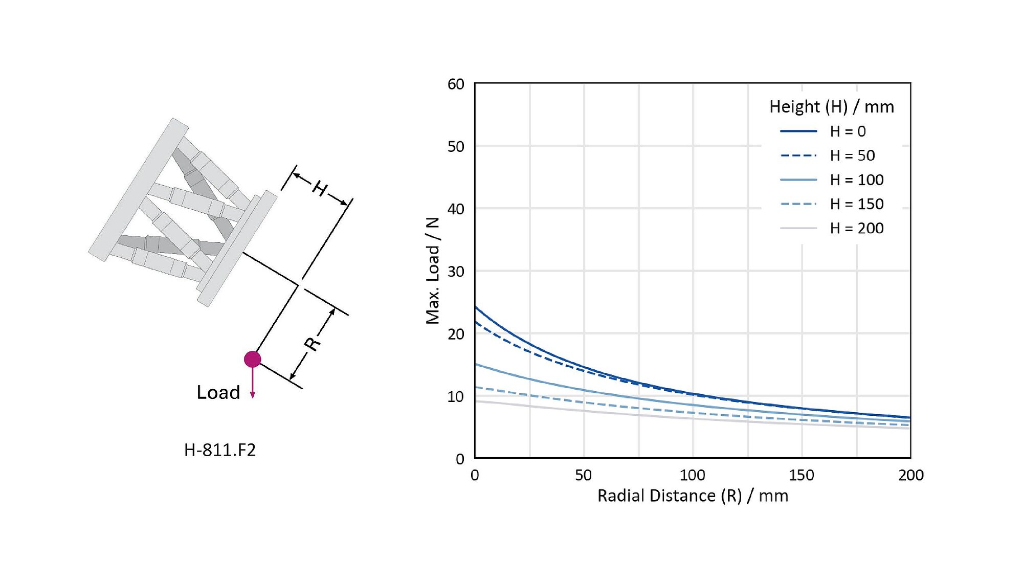
H-811.F2を最も不利な角度で取り付けた場合の最大荷重
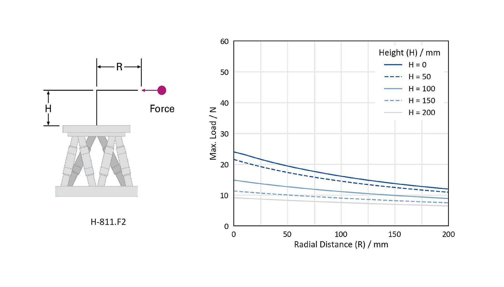
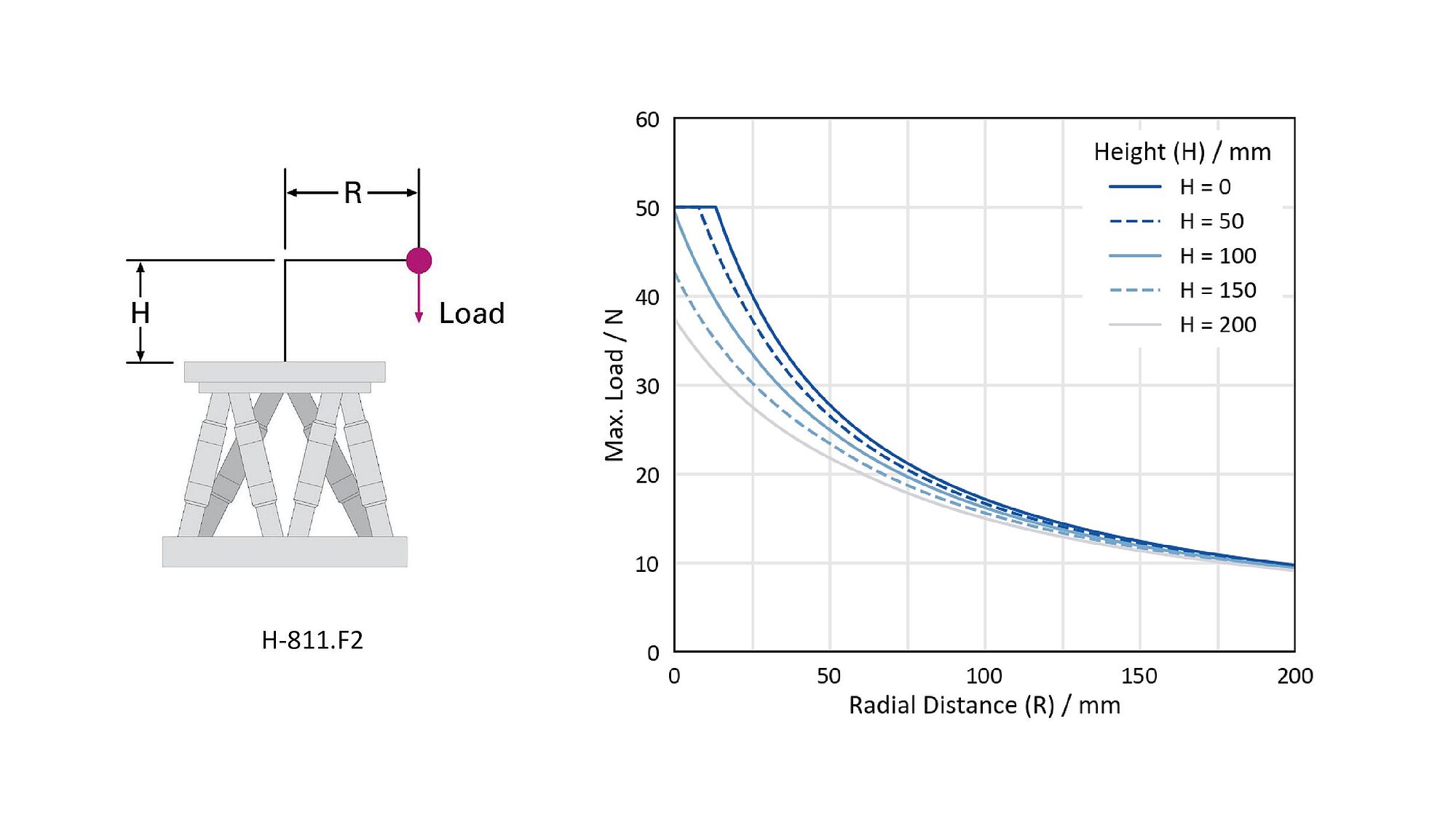
H-811.F2を水平に取り付けた場合の最大許容力
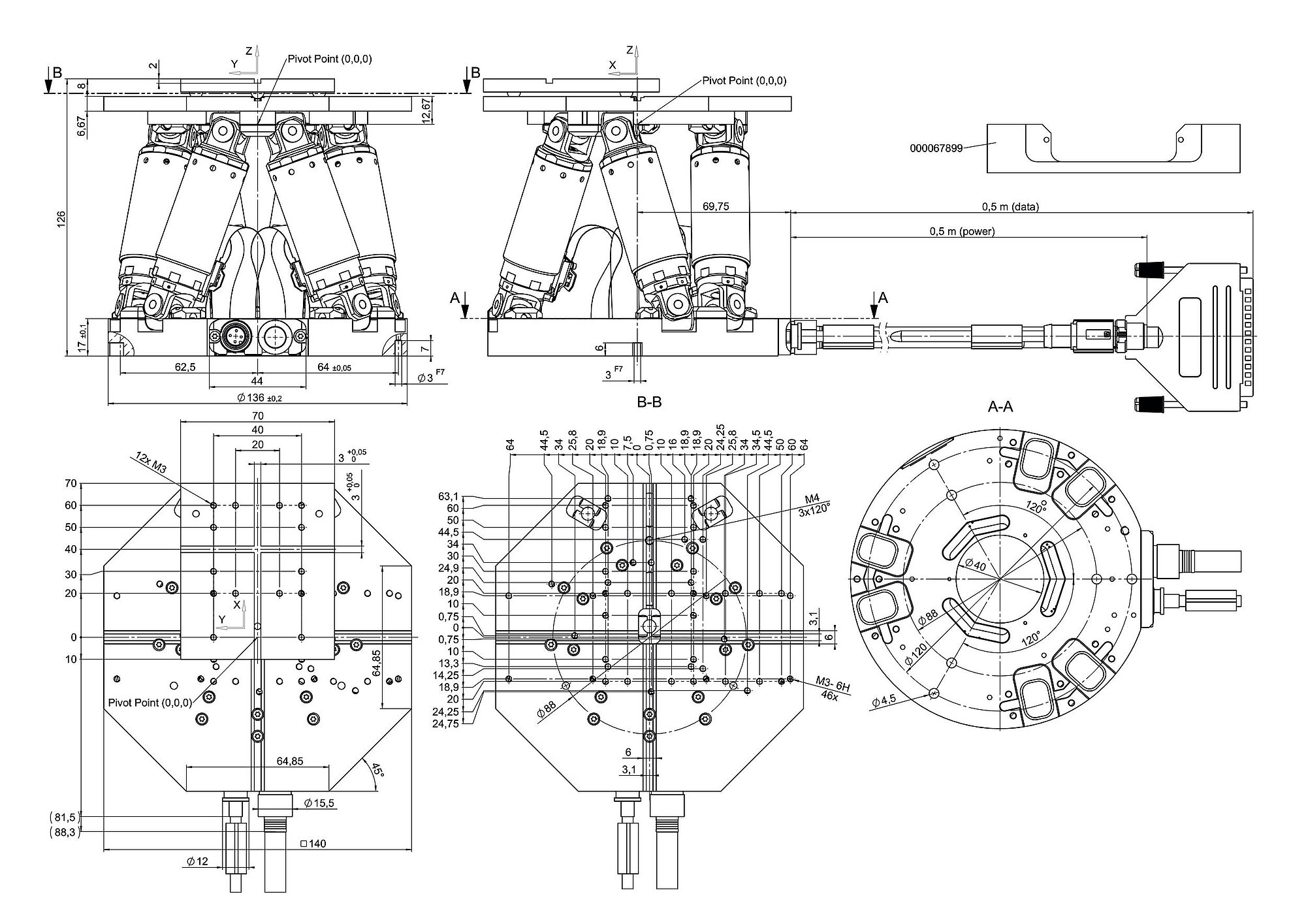
H-811.F2、寸法(単位:mm)。公称トラベルレンジが0の場合の寸法です。 図面では小数点の代わりにコンマが使用されていることに注意してください。
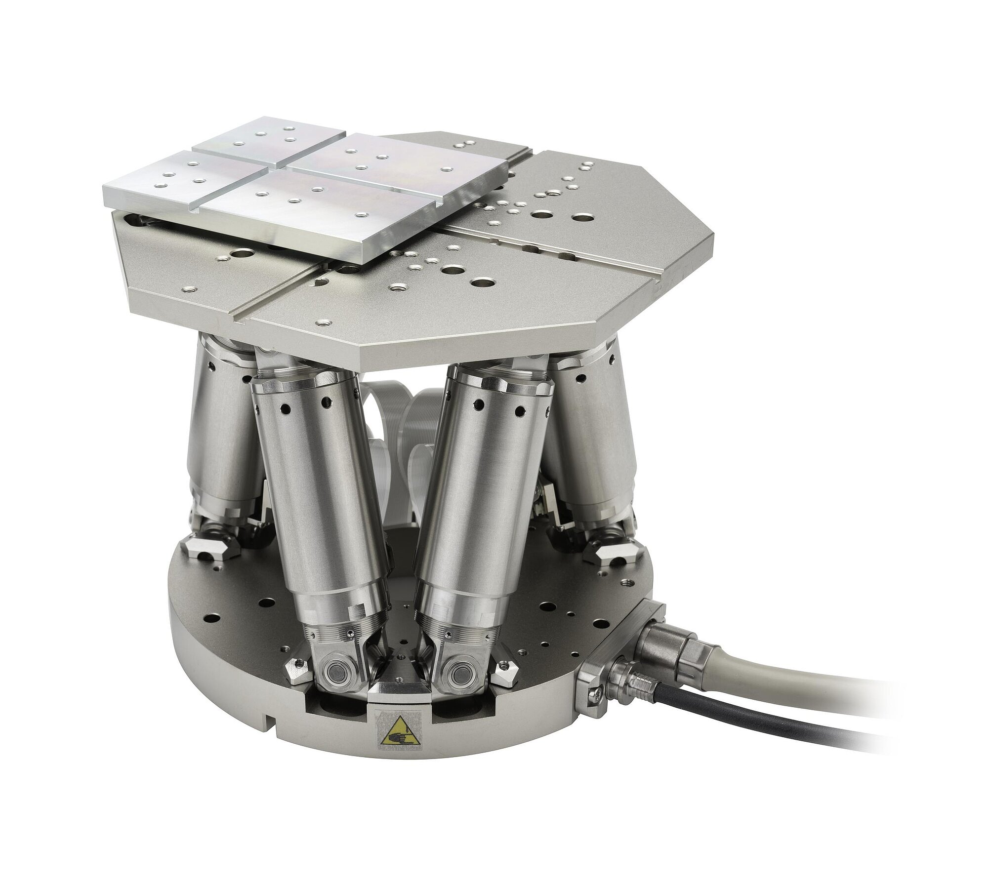
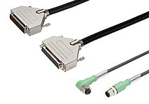
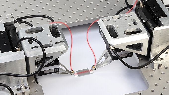
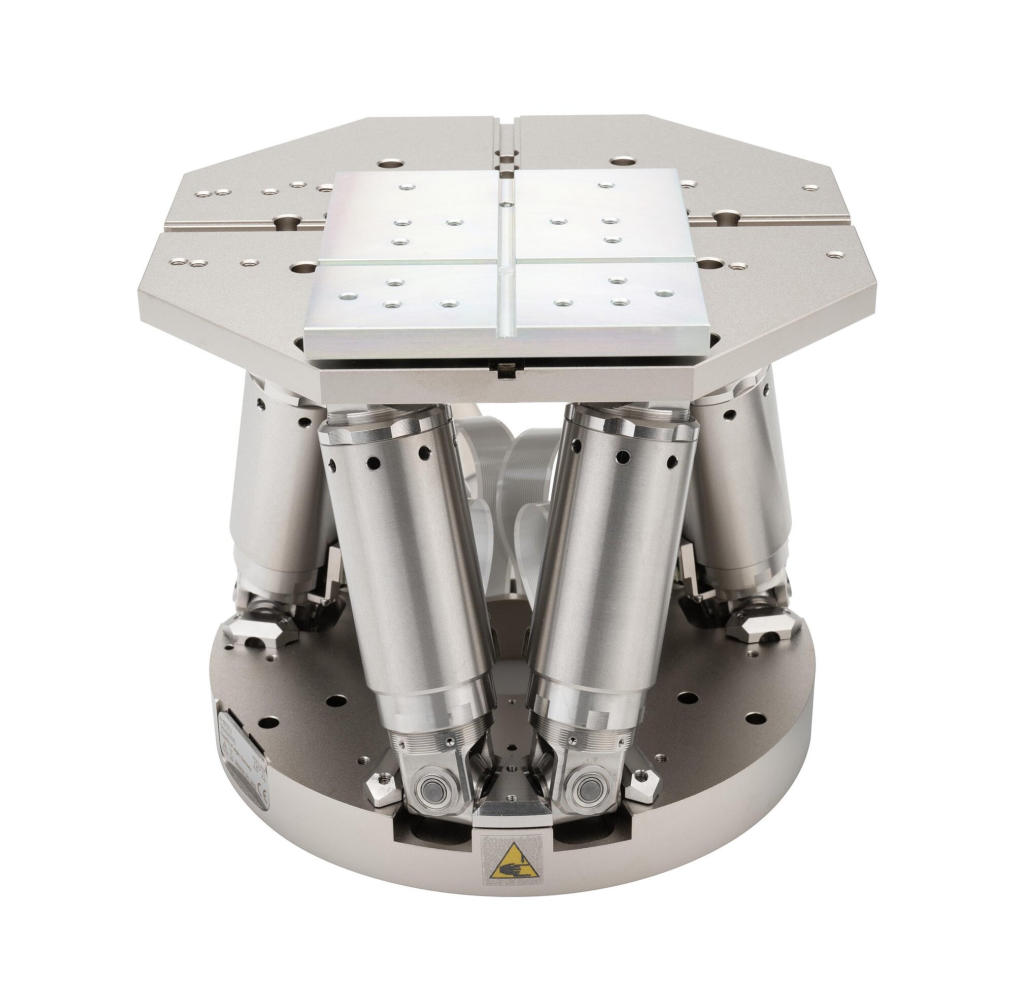
ケーブル導出部及びH-811.F2の外観


応用分野
H-811.F2は、磁気によって保持される取り付けプレートにより、ファイバーや光学部品のアライメントに特に適しています。 H-811は、設置面積が小さく、サイクル数の多い用途における実績ある信頼性により、フォトニクス分野で積極的に採用されています。 この分野では、H-811は複雑な製造プロセスや測定手順の生産性向上に大きく貢献します。
高いダイナミクスと信頼性の融合
パラレルキネマティック配置により、本ヘキサポッドはコンパクトな設計ながらも6軸の動作を実行できます。 H-811は、ブラシレスDCモーターの採用と剛性の高い機械設計により、外部干渉が生じる状況(例えば接着工程など)においても、アクティブアライメント用途に必要なダイナミクスを提供します。 幅広いソフトウェアツールは、システムチューニングを簡素化し、外部アナログ制御信号へのアライメントのための自動ルーチンも利用可能です。
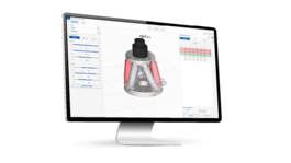
システム全体を保護するための動作シミュレーション
無償でダウンロード可能なPIVirtualMoveソフトウェアは、H-811のトラベルレンジ、アライメント、許容力、トルクをシミュレーションし、最適なシステム構成の実現に役立ちます。 このシミュレーションでは、選択した回転中心と荷重重心の両方が考慮されます。
ワーク・ツール座標系や、エミュレーションツールは、ヘキサポッドコントローラーに同梱されている無償ソフトウェアパッケージに含まれています。 これらのツールは、光学部品やフォトニック部品などの重要な部品の保護に役立ちます。
| Motion | H-811.F2 | Tolerance |
|---|---|---|
| Active axes | X ǀ Y ǀ Z ǀ θX ǀ θY ǀ θZ | |
| Travel range in X | ± 17 mm | |
| Travel range in Y | ± 16 mm | |
| Travel range in Z | ± 6.5 mm | |
| Rotation range in θX | ± 10 ° | |
| Rotation range in θY | ± 10 ° | |
| Rotation range in θZ | ± 21 ° | |
| Maximum velocity in X | 20 mm/s | |
| Recommended velocity in X | 10 mm/s | |
| Maximum velocity in Y | 20 mm/s | |
| Recommended velocity in Y | 10 mm/s | |
| Maximum velocity in Z | 20 mm/s | |
| Recommended velocity in Z | 10 mm/s | |
| Maximum angular velocity in θX | 500 mrad/s | |
| Recommended angular velocity in θX | 250 mrad/s | |
| Maximum angular velocity in θY | 500 mrad/s | |
| Recommended angular velocity in θY | 250 mrad/s | |
| Maximum angular velocity in θZ | 500 mrad/s | |
| Recommended angular velocity in θZ | 250 mrad/s | |
| Positioning | H-811.F2 | Tolerance |
| Minimum incremental motion in X | 0.2 µm | typ. |
| Minimum incremental motion in Y | 0.2 µm | typ. |
| Minimum incremental motion in Z | 0.08 µm | typ. |
| Minimum incremental motion in θX | 2 µrad | typ. |
| Minimum incremental motion in θY | 2 µrad | typ. |
| Minimum incremental motion in θZ | 3 µrad | typ. |
| Unidirectional repeatability in X | ± 0.15 µm | typ. |
| Unidirectional repeatability in Y | ± 0.15 µm | typ. |
| Unidirectional repeatability in Z | ± 0.06 µm | typ. |
| Unidirectional repeatability in θX | ± 2 µrad | typ. |
| Unidirectional repeatability in θY | ± 2 µrad | typ. |
| Unidirectional repeatability in θZ | ± 3 µrad | typ. |
| Backlash in X | 0.2 µm | typ. |
| Backlash in Y | 0.2 µm | typ. |
| Backlash in Z | 0.06 µm | typ. |
| Backlash in θX | 2 µrad | typ. |
| Backlash in θY | 2 µrad | typ. |
| Backlash in θZ | 3 µrad | typ. |
| Integrated sensor | Incremental rotary encoder | |
| Drive properties | H-811.F2 | Tolerance |
| Drive type | Brushless DC motor | |
| Mechanical properties | H-811.F2 | Tolerance |
| Stiffness in X | 0.7 N/µm | |
| Stiffness in Y | 0.7 N/µm | |
| Stiffness in Z | 8 N/µm | |
| Maximum load capacity, base plate horizontal | 5 kg | |
| Maximum load capacity, base plate in any orientation | 2.5 kg | |
| Maximum holding force, base plate horizontal | 12 N | |
| Maximum holding force, base plate in any orientation | 2 N | |
| Overall mass | 2.2 kg | |
| Material | ステンレススチール、アルミニウム | |
| Miscellaneous | H-811.F2 | Tolerance |
| Operating temperature range | 0 to 50 °C | |
| Connector for data transmission | HD D-sub 78 (m) | |
| Connector for supply voltage | M12 4-pole (m) | |
| Cable length | 0.5 m | |
| Outer diameter power supply cable | 4.95 mm | |
| Minimum bending radius for fixed installation, power supply | 25 mm | |
| Outer diameter data transmission cable | 9.5 mm | |
| Minimum bending radius for fixed installation, data transmission | 95 mm | |
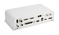
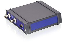
| Recommended controllers/drivers | C-887.5x |
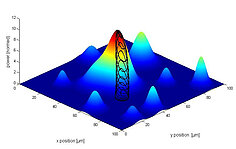
スキャン時間:領域全体をスキャンして最高強度に移行するまでの平均所要時間
最大耐荷重と最大保持力に関する注意:規定された値は、取り外し可能な磁気プレートのないヘキサポッドに適用されます。
H-811.F2に固定されているケーブルの長さは、それぞれ0.5 mです。
H-811.F2に固定されているケーブルは、ドラッグチェーン非対応です。
接続ケーブルは同梱されていませんので、別途ご注文ください。
カスタマイズについてはお問い合わせください。
When measuring position specifications, typical velocity is used. The data is included in the delivery of the product in the form of a measurement report and is stored at PI.
The maximum travel ranges of the individual coordinates (X, Y, Z, θX, θY, θZ) are interdependent. The data for each axis shows its maximum travel range when all other axes are in the zero position of the nominal travel range and the default coordinate system is in use, or rather when the pivot point is set to 0,0,0.
PI では、技術データは 22 ±3 ℃ において規定されています。 記載がない限り、数値は負荷のない条件のもとにあります。 一部の特性は相互に依存しています。 「typ.」の表記は、特性の統計的な平均値を示すものであり、供給されるすべての製品に対して保証値を示すものではありません。 製品の最終検査では、すべての特性ではなく、選択された特性のみが分析されます。 一部の製品特性は、使用時間の増加に伴って劣化する可能性がある点にご注意ください。
H-811 Miniature Hexapods
Technical note for unpacking the hexapod
必要な数量、価格、およびリードタイムに関する無料の見積を依頼するか、必要な編集について説明します。オンラインで提供されるすべての製品は直接発注できます。
光学アライメント用の小型ヘキサポッド、取り外し可能な磁気プレート、ブラシレスDCモーター搭載、耐荷重:5 kg、速度:20 mm/s、ケーブル長:0.5 m。 接続ケーブルは同梱されていませんので、別途ご注文ください。